
Technology
Rigid Chain Technology
The Engineering Science of Push-Pull Linear Actuation.
Overview
For over 50 years, SERAPID has pioneered, refined, and industrialised a class of electromechanical linear actuator that is unlike any other: Rigid Chain Technology (RCT). Where conventional chains can only pull, and where screw jacks and hydraulic cylinders require retraction space equal to their working stroke, SERAPID’s Rigid Chain can push and pull, extend without drift, and retract into a compact magazine that occupies a fraction of the deployed column length. The result is a mechanically deterministic, oil-free, zero-backlash linear actuator capable of moving loads ranging from a few kilograms to several hundred metric tonnes — with repeatability measured in fractions of a millimetre.
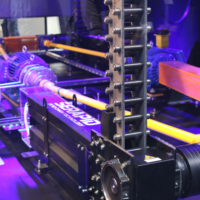
The Mechanics of a Self-Locking Kinetic Column
The defining characteristic of SERAPID Rigid Chain Technology is its ability to function simultaneously as a flexible, stowable element and a rigid, load-bearing column — a duality that conventional linear actuators cannot achieve. Understanding how this is possible requires examining the geometry and mechanics of each individual link, the interface between links, and the system-level behaviour of the assembled chain during deployment and retraction.
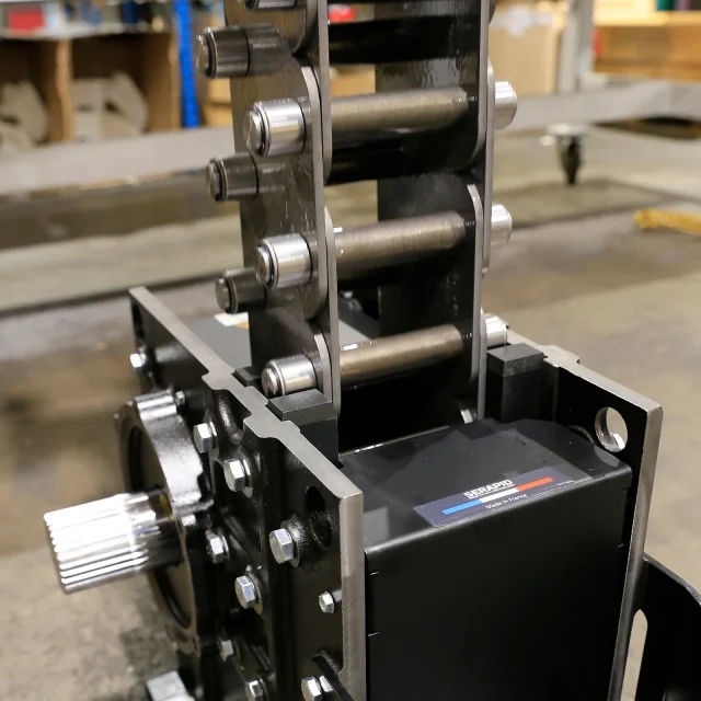
Each link in an RCT chain is a precision-machined steel component with two functional axes: the articulation axis (cross-axis) and the thrust axis. On the articulation axis, conventional cylindrical rollers connect adjacent links via hardened pins, allowing the chain to flex and coil during retraction into the magazine. This axis is geometrically identical to a high-performance industrial roller chain and is governed by the same stress and fatigue criteria.
The distinguishing feature is a hook-like extension, known as the shoulder, that projects from the lateral face of each side plate. When two consecutive links are driven into the forward (deployed) position and exit the drive housing, the shoulder of the trailing link bears against the recessed seat of the leading link. The contact geometry creates a positive mechanical interlock: compressive thrust force is transmitted link-to-link through these bearing faces, not through the pin-and-roller system. The column therefore behaves as a homogeneous compression bar with a stiffness and Euler buckling load that scales with chain cross-section and guided length.
At the head of the column, a specially designed front link shifts the resultant thrust vector above the articulation axis. This geometric offset produces a moment that draws the shoulders into firm contact, self-locking the column under load.
SERAPID manufactures the chain in multiple strand configurations, each optimised for specific load classes and spatial envelopes:
- Simplex (standard): two rows of link plates and two rows of shoulders. Suitable for light-to-medium loads in compact systems.
- Duplex: three rows of link plates. Increases the bearing area of the shoulder interfaces, directly raising the allowable compressive force and buckling resistance.
- Joined / reinforced: two mirroring simplex plates riveted or assembled together. A cost-effective route to the strength of a thicker section without full duplex tooling.
Side plates may be cranked (offset) or flat. Cranked plates provide the shoulder extension within the plate height, minimising overall chain width. Flat plates with a separate shouldered component are used in specialist high-load variants where the contact surface demands a larger bearing zone.
Chain size is defined by the pitch, measured as the centre-to-centre distance between consecutive articulation axes. SERAPID’s standard pitch series is 40 mm, 60 mm, and 90 mm. Larger pitch means more bearing area per link, higher allowable shoulder contact stress, greater inter-link clearance for thermal expansion, and a larger central roller that can carry heavier radial loads in the guide system. The pitch also governs the polygon effect: with a 6-tooth pinion, the velocity uniformity of a 40 mm pitch chain is identical to that of a 90 mm pitch chain, because the ratio of link pitch to pinion pitch circle diameter is held constant across the series through matched sprocket design.
Drive Housing and Sprocket Engineering
The drive housing is not merely a structural frame; it is the kinematic transformer that converts rotary motor output into the push-pull force of the rigid chain column. Four engineering domains intersect inside this compact assembly: sprocket geometry, internal plate guidance, drive ratio selection, and tooth contact mechanics.
Unlike a conventional roller chain drive where the sprocket may carry 12 to 24 teeth, SERAPID rigid chain drive pinions operate with a very low tooth count — typically 6 teeth. This is not a limitation but a deliberate design parameter with cascading benefits:
- Compact housing: a 6-tooth pinion has the smallest possible pitch circle diameter for a given pitch, minimising the bend radius that the chain must negotiate when transitioning from the coiled magazine into the deployed column. A smaller bend radius means a shorter blind stroke, which directly reduces chain inventory for a given useful stroke.
- Uniform velocity output: with exactly 6 teeth, the pinion makes one full revolution for every 6 links of chain output. For a 40 mm pitch chain this is 240 mm per revolution; for a 60 mm pitch, 360 mm; for a 90 mm pitch, 540 mm. These integer relationships simplify motion controller programming.
- High force transmission: tangential force on the chain equals motor torque divided by the pinion pitch circle radius. A smaller radius increases force for the same torque, enabling compact gearmotor packages to drive very large loads without auxiliary power stages.
Tooth form on RCT pinions is not a standard ANSI or ISO roller chain profile. SERAPID designs the tooth flanks to engage exclusively with the articulation axis rollers, ensuring that locking geometry is not disrupted by the meshing kinematics. Pinion materials are selected for case-hardened surface hardness (typically 58–62 HRC) over a tough core.
Inside the drive housing, the chain follows a precision-formed path defined by two sets of plates. The guide plates constrain the articulation-axis rollers laterally, preventing the chain from wandering sideways as thrust builds. The reaction plates bear the back-pressure of the deployed column: when the chain is transmitting maximum compressive force, the reaction on the last link engaged by the pinion is equal to the total column thrust force, and this force is transferred into the housing structure through the reaction plate bearing face.
Clearance between the central rollers and the guide/reaction plate channel surfaces is controlled to within tenths of a millimetre. This tight tolerance is the principal source of the sub-5 mm lateral positioning accuracy that SERAPID systems demonstrate over strokes exceeding 7 metres in unguided operation.
Drive ratio in a rigid chain system is the relationship between motor shaft rotational speed and chain linear output speed, and it must reconcile three competing requirements: motor speed (typically 1 400–3 000 RPM), required chain speed (often 0.01 to 0.5 m/s for precision positioning, up to 1.5 m/s for fast industrial transfer), and torque demand.
SERAPID engineers have mastered the pairing of motor, gearbox, and pinion as a matched set for each application. This systems-level approach allows SERAPID to achieve drive ratios precisely tuned to the intersection of the motor’s maximum efficiency region and the gearbox’s rated output torque. For high-force, low-speed applications (nuclear waste transfer, stage platform lifts), a high overall ratio (typically 50:1 to 200:1) places motor operation in the middle of its torque-speed curve. For high-speed industrial transfer, a lower overall ratio (10:1 to 40:1) allows the motor to deliver rapid cycle times.
Because SERAPID specifies the pinion tooth count and pitch in-house, it can fine-tune the last-stage mechanical advantage without modifying the gearbox ratio — a degree of freedom that competitors relying on standard chain drives cannot access.
Contact ratio in a rigid chain drive — defined as the number of link rollers simultaneously engaged with sprocket teeth during power transmission — is a critical determinant of instantaneous load per tooth and long-term wear life. In a conventional roller chain drive, the sprocket sits at the centre of the chain’s curve, engaging rollers from the inside of the bend. SERAPID’s drive architecture is fundamentally different: the pinion engages the chain from the outside of the curve, bearing against the rollers on the convex face of the chain’s path through the housing.
This external engagement geometry maintains positive roller-tooth engagement across a larger arc of the pinion’s rotation, maximising the effective contact ratio and distributing total thrust force across multiple teeth at once — dramatically reducing the Hertzian contact stress per tooth face.
No other manufacturer in the rigid chain market has implemented this outside-engagement sprocket architecture with the same degree of geometric optimisation — giving SERAPID the highest effective contact ratio, the lowest per-tooth stress, and consequently the longest sprocket service life available in the industry.
Choose a Pitch Chain Circle Diameter
Full revolution distance (6-tooth pinion)
6 links of chain output → 6 x 40 mm = 240 mm per revolution
6 links of chain output → 6 x 60 mm = 360 mm per revolution
6 links of chain output → 6 x 90 mm = 540 mm per revolution
R&D Excellence and Destructive Testing Methodology
SERAPID’s engineering credibility rests not only on 50+ years of field installations but on a systematic programme of laboratory validation that directly informs the rated capacities published in its product literature. The programme has three pillars:
Each chain series undergoes axial compressive proof testing at multiple stroke lengths (e.g., 0.5 m, 1 m, 2 m, 4 m unguided; then guided equivalents). Load is applied in a calibrated universal testing machine at a controlled displacement rate. The test proceeds past yield and to complete instability (buckling collapse), generating a force-displacement curve that fully characterises the elastic, post-elastic, and failure regimes. The published rated capacity is set at a fraction of the experimentally determined elastic limit, using safety factors consistent with ISO 4301 and FEM crane design standards.
The pull function of RCT relies on the pin-roller-plate assembly in pure tension, and SERAPID validates tensile fatigue life using pulsating load tests per ISO 606 (short-pitch transmission precision roller chains) and the more stringent SERAPID internal test protocol. A representative sample of chain is cycled between a mean load and a peak load at the application frequency (typically 0.1 to 5 Hz for industrial lifts), and the number of cycles to crack initiation is recorded. S-N (Wöhler) curves are constructed for each alloy and pitch combination, establishing the fatigue endurance limit that underpins the rated pull capacity.
A complete drive housing assembly, including sprocket, guide plates, and reaction plates, is operated at rated load and duty cycle on a test rig instrumented with load cells, position encoders, and temperature sensors. Pin and roller wear is measured at intervals using co-ordinate measuring machine (CMM) inspection of sectioned samples. This data feeds back into the lubrication specification and the maintenance interval tables published in SERAPID installation manuals. For the HDLift product line — the “heavy duty” variant designed for cycle frequencies exceeding a threshold that would stress standard RCT components — the drive cycle test is extended to simulate the full design-life cycle count, including simulated emergency stops (instantaneous deceleration loads) and blocked-load events. SERAPID’s investment in this multi-axis validation approach means that when a design engineer specifies a SERAPID actuator, the safety factor is not a theoretical estimate derived from material handbooks alone, but a margin over experimentally confirmed failure loads. In safety-critical applications — nuclear, aerospace, military — this distinction is decisive.
Engineering Design Process and Support
SERAPID’s engineering team, with over 50 years of application experience, follows a structured design process for every new system:
- Load analysis: determination of all force components (weight, friction, acceleration, deceleration, external loads), identification of combined and worst-case loading scenarios.
- Chain selection: comparison of required force against the rated capacity curve for each pitch and strand configuration, accounting for stroke length and guide status.
- Drive train sizing: iterative selection of motor, gearbox ratio, and pinion geometry to match the motor operating point to its rated continuous torque region, with thermal margin for the application duty cycle.
- Magazine and housing layout: optimisation of the chain storage configuration (vertical, horizontal, or 90° redirect) within the available space envelope, using SERAPID’s proprietary catalogue of drive housing variants.
- System integration: specification of sensors, encoders, safety brakes (if required by lift directive), and control interfaces for PLC or servo drive integration.
This process is supported by published technical literature and application questionnaires available from SERAPID application engineers worldwide.
Comparison with Competing Linear Actuation Technologies
Hydraulic cylinders achieve high force density but require a continuous-pressure fluid circuit, oil reservoir, pump, valves, seals, and — for vertical loads — a counterbalance valve to prevent drift on power loss. SERAPID RCT is electromechanical: it is inherently self-locking under any load when the motor is de-energised, requires no fluid infrastructure, produces zero risk of hydraulic oil leakage (critical in food, pharmaceutical, marine, and nuclear environments), and consumes energy only when moving a load. Life-cycle operating cost advantage over hydraulic systems has been validated at SERAPID field installations over decades of continuous operation.
Learn more with our blog: Articles
Screw jacks are self-locking and mechanically deterministic but carry a fundamental disadvantage for long-stroke applications: the screw must be as long as the stroke, meaning a 3 m stroke requires a 3 m screw to be always housed within the machine footprint. SERAPID RCT stores the chain in a compact magazine (height approximately 10–15% of stroke length for typical configurations), making it the only viable electromechanical solution where the installation depth below or beside the load is constrained. Screw jack efficiency is also limited to 30–50% due to thread friction, while RCT drive efficiency at rated load typically exceeds 80%.
Standard roller chains can only transmit tensile force; a separate return chain or cable is required for push-pull operation, doubling the chain inventory and the number of drive pinions. RCT achieves bidirectional force transmission in a single chain strand by separating the tensile and compressive load paths at the geometric level of the link itself.
Product Applications and Validated Deployments
SERAPID’s LinkLift family spans load capacities from approximately 0.5 kN to over 500 kN per column, with strokes limited only by magazine geometry and column guide provisions. The HDLift line extends these capabilities into high-frequency duty cycle regimes, validated for continuous industrial operation in automotive press shops, aircraft assembly jigs, and ship-loading equipment. Multiple columns can be synchronised electronically, enabling level-critical applications such as the lifting of large structural modules where differential height error must remain below 1 mm across a span of tens of metres.
For architectural, telecommunications, and defence applications requiring column heights above 5 metres, SERAPID’s ChainMast integrates RCT into a self-supporting guiding structure. The MultiMast range variant may combine two, three, or four TeleMasts in mechanical synchronisation, enabling lifting of large rigid loads (e.g. stage roofs, antenna arrays, military sensor masts) with controlled tilt and level monitoring.
SERAPID’s horizontal RCT products extend the push-pull principle to in-plane transfer of loads up to 160 kN over strokes of up to 10 metres. Applications include die transfer in metal stamping presses (the Quick Die Change / QDX product line), nuclear waste carriage transfer, and automated storage and retrieval systems. The zero-drift hold capability — the actuator remains at position without motor power and without a brake — is invaluable in press environments where tooling must be locked at transfer height against gravity and vibration.
SERAPID’s QSX seating system uses RCT columns to raise and lower raked seating modules in multipurpose venues, achieving reconfiguration from flat floor to fully raked auditorium in under 15 minutes. The Zaryadye Park Philharmonic Concert Hall in Moscow, opened 2018, features the first curved-row QSX installation in the world — twenty curved rows of 677 seats — demonstrating that the engineering precision of RCT transfers directly from industrial settings to architectural applications with the highest demands for silent, smooth, and reliable operation.